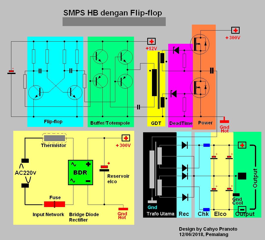
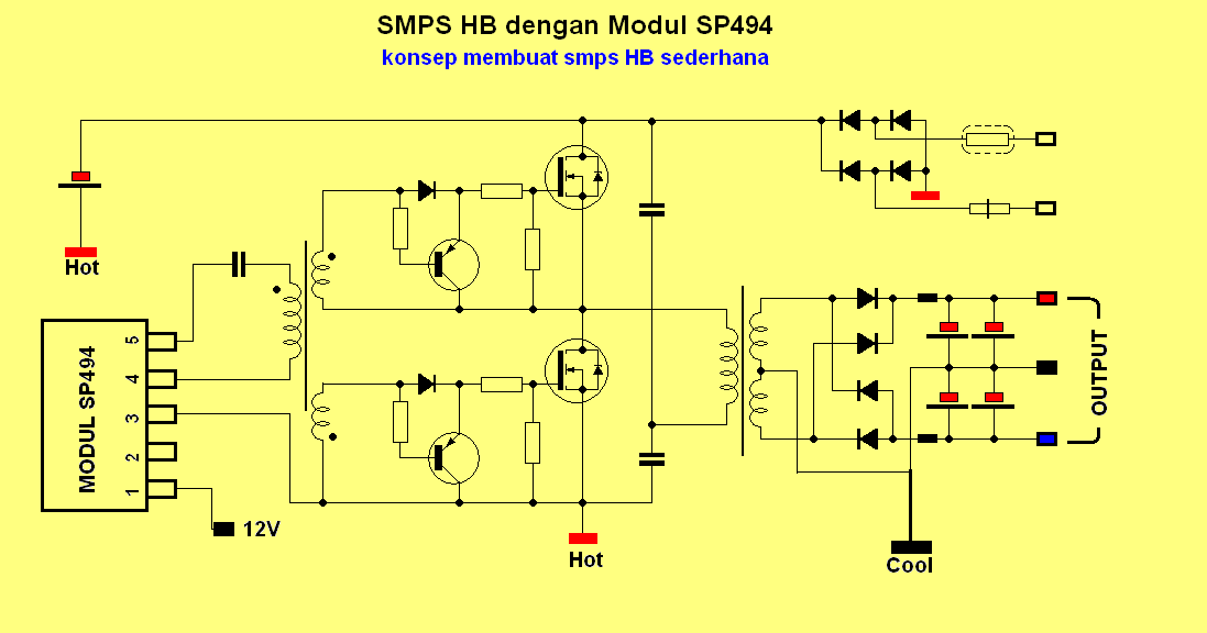
Skema Smps Hb Sederhana
Switching Mode Power Supply (SMPS) has become a standard type of power supply unit for electronic devices because of their high efficiency, low cost and high power density. The following image shows an SMPS unit from an old desktop computer. This particular SMPS is rated for 90W of power. Linear Regulator vs. SMPS What is the purpose of SMPS?

Smps Circuit Diagram Pdf
the asymmetrical half bridge needs a floating gate drive for the high side switch. Figure 10: Half bridge asymmetrical forward converter * Power switch: V CEV or V DSS ≥ V inmax * Rectifiers: FORWARD D1: V inmax (V out + V F) V inmin. δ max V RRM ≥ I F(av) ≥I out.δ max FREEWHEELING D2: V RRM ≥V inmax (V out + V F) I F(av) ≥I out 1.2.

Smps Full Bridge fishfasr
supplies. It also provides real SMPS examples, and identifies several application notes and additional design resources available from ON Semiconductor, as well as helpful books available from various publishers and useful web sites for those who are experts and want to increase their expertise.

full bridge HV buck smps EasyEDA open source hardware lab
5 Skema Smps Full Bridge Terbaru October 20, 2021 With a 220v mains input, the frequency before the bridge would be 50hz (standard grid spec), and after rectification this is supposed to become double that is at 100hz. Skema Power Supply Tv China - TV Schematics from 3.bp.blogspot.com
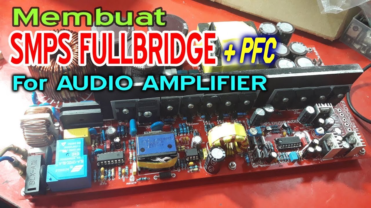
Cara Membuat SMPS FULLBRIDGE PFC YouTube
FULL-BRIDGE-SMPS Last Updated: Jun 8, 2023 The full-bridge DC-DC switch mode power supply reference design is based on V series MCUs and intended to provide the example of power conversion applications. The full-bridge DC-DC converter is a transformer-isolated buck converter. The full-bridge topology contains full-bridge

full bridge HV buck smps EasyEDA open source hardware lab
SMPS FULLBRIDGE PFC Schematic + PCB Layout PDF - Electronic Circuit Home / Power Supply Circuit SMPS FULLBRIDGE PFC Schematic + PCB Layout PDF By Electronics Hobbyist Tuesday, January 03, 2023 33 comments Hello DIY'ers, I will share the schematic and PCB layout for Fullbridge with PFC (Power Factor Correction) Switching Mode Power Supply.
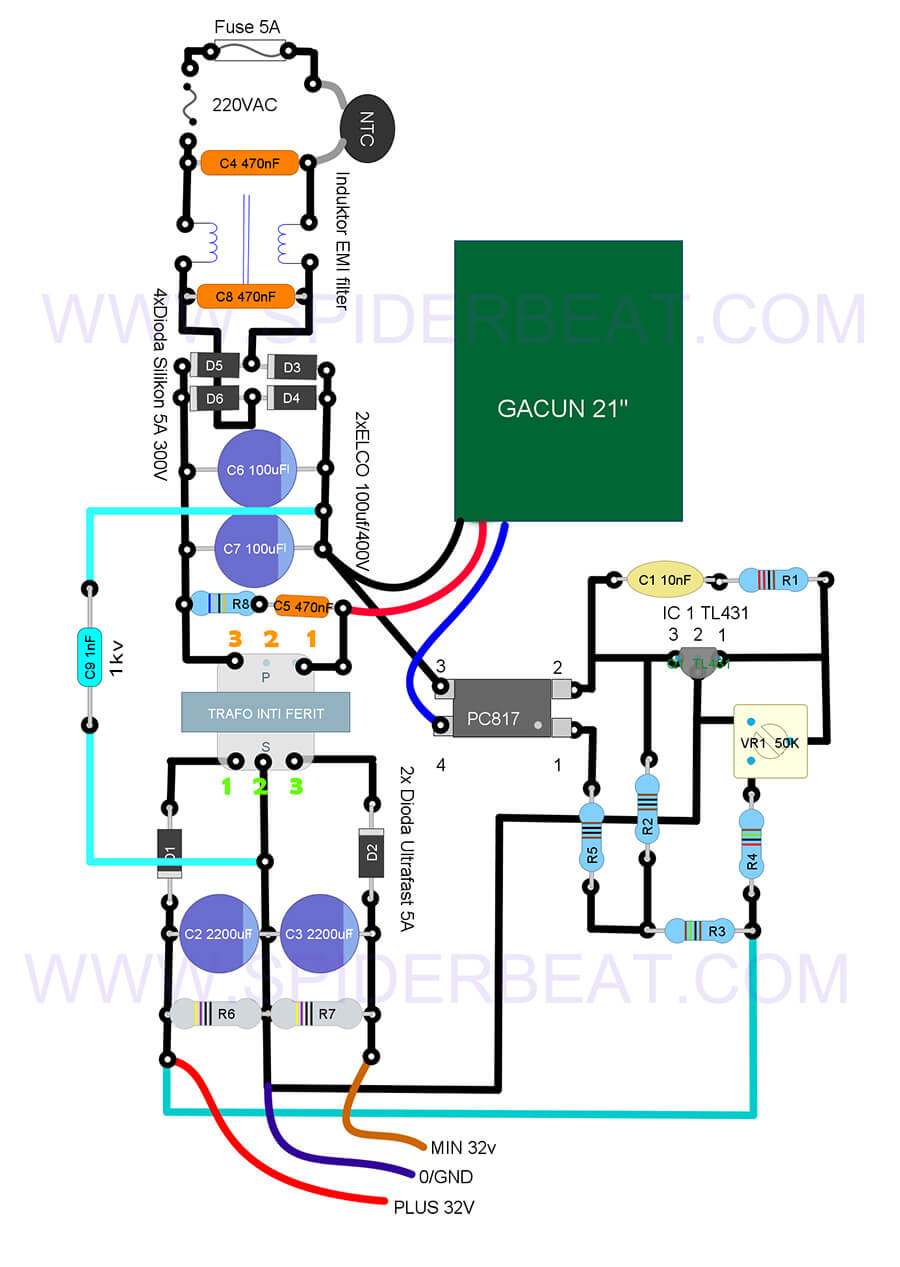
Cara Membuat SMPS Dari Gacun CT Untuk Power Amplifier Yang Stabil
The flyback design is a switched-mode power supply (SMPS) that's been used for 70+ years and still going strong. This supply—also called a power converter—has two distinct operating phases.

Skema Switching SMPS LG CRT Monitor 15 Inchi Tutorial, Desain & Hoby
1. For PWM frequency adjustment 30-130kHz 2. Duty cycle adjustment 30-40% Low Side gate adjustment 3. Overcurrent adjustment sensitivity 4. Aux DC out adjustment PWM Gate signal at 82kHz and Duty Cycle 38.1% Transformer Ferrite EE55/28/21 Np Working Frequency 30-40kHz = 18 turns 40-50kHz = 16 turns 50-60kHz = 15 turns 60-80kHz = 14 turns
Terbaru 45+ Skema Smps Las, Skema Las
This paper presents a high-efficiency AC-DC switch-mode power supply (SMPS) using the full-bridge converter circuits. The proposed converter utilizes three full-bridge converter circuits: two full-bridge diode converter circuits and one full-bridge MOSFET converter circuit. The two full-bridge converters are utilized at the primary AC input and.

Smps Full Bridge fishfasr
Figure 1 shows a simplified circuit of a phase shifted full bridge. MOSFET switches QA, QB, QC and QD form the full-bridge on the primary side of the transformer T1. QA and QB are switched at 50 % duty and 180 degree out of phase with each other. Similarly, QC and QD are switched at 50 % duty and 180 degree out of phase with each other.

smps full bridge sos EasyEDA open source hardware lab
SMPS FULLBRIDGE PFCF OLD SMPS FULLBRIDGE PFC VERSI OLD Bagi yg mau mencoba merakitntya file sprint layout nya bisa di download disini. http://fumacrom.com/3oxJA f. NEW SMPS HALFBRIDGE+OCP BY CKM TRONIK SMPS HalfBridge 2.5kva dengan mengunakan osc SOS.dan sudah saya lenkapi dengan OCP+OVP dan SOFTSTART. 1.OCP..pungsinya jika terjadi shor.
Skema SMPS Gacun Lengkap dengan Cara Membuatnya
The crucial hurdle in a full bridge or a H-bridge design is the incorporation of 4 N-channel mosfet full bridge topology, which in turn demands the incorporation of a bootstrap mechanism for the high side mosfets. What's Bootstrapping

Full Bridge Smps Circuit Diagram
To the east stands the Pennsylvania Railroad bridge (1965-1966), at the time the third-longest railroad lift bridge in the world and cited for excellence by the American Institute for Steel Construction. An intriguing iron pivot bridge (1852) just north of the railroad bridge was unfortunately removed in 1967.

SKEMA SMPS BERBAGI ITU INDAH YouTube
Typical full bridge driver connection diagram. Decades of application expertise and technology development at both Infineon and International Rectifier have produced a portfolio of gate driver ICs for use with silicon and wide-bandgap power devices, such as MOSFETs, discrete IGBTs, IGBT modules, SiC MOSFETs and GaN HEMTs. We offer excellent.

Pcb SMPS Full Bridge Pfc
We're building another Full Bridge converter… but this one is different! Designing for a wide input range is not an easy task, but that's the challenge we're.

Audio Kreatif SKEMA SMPS 1200WATT
2013-11-15 6:45 pm. #1. I am working on a full bridge boost converter capable of putting 900 watts into a load. This is based upon TL494 pwm generator from Texas instruments. TL494 is made to work in complementary output logic. But there is a little problem with the mosfet deriving stage. I am using the standard circuit given in the datasheet.